For our final project this semester, my friend Nathaniel and I built a color organ, a multi-sensory device that produces a light show correlated to music or sound. The concept of “color music” first emerged in the 1500s, and color organs have since become more complex and responsive to the intricacies of a piece of music, reaching a popularity peak in the 1970’s disco scene (hence our project’s unofficial name - Seventies-Style Sight and Sound System, or S^5).
We did this entirely using analog circuitry, transforming an input audio signal into LED lighting corresponding to the signal’s frequency band. Key features include volume control, implemented using an operational amplifier, which allows the user to adjust the volume of the output signal, and a series of active bandpass filters that separate the audio into three bands: low, medium, and high frequency.
Block Diagram
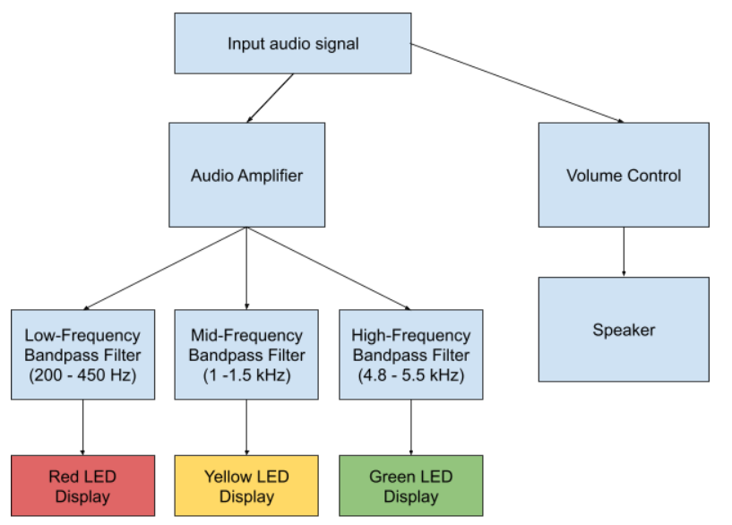
Block Diagram of the SSSSS
There are four main components: input signal, amplification, filtering, and output. The input signal was inserted with a 3.5 mm stereo plug (so you can play a song on a phone or computer). In order to produce the output LED display, the signal was amplified with a transistor amplifier and filtered into its different compositional frequencies with bandpass filters. Depending on the filter, the signal was sent to either the red LEDs (low frequencies), yellow LEDs (medium frequencies), green LEDs (high frequencies) to be displayed. A color organ requires that the user have the full experience of listening to music in addition to watching flashing LED lights, so the signal was also sent to a speaker. Volume control was also implemented so that the user can adjust the volume level to their preference.
Schematic
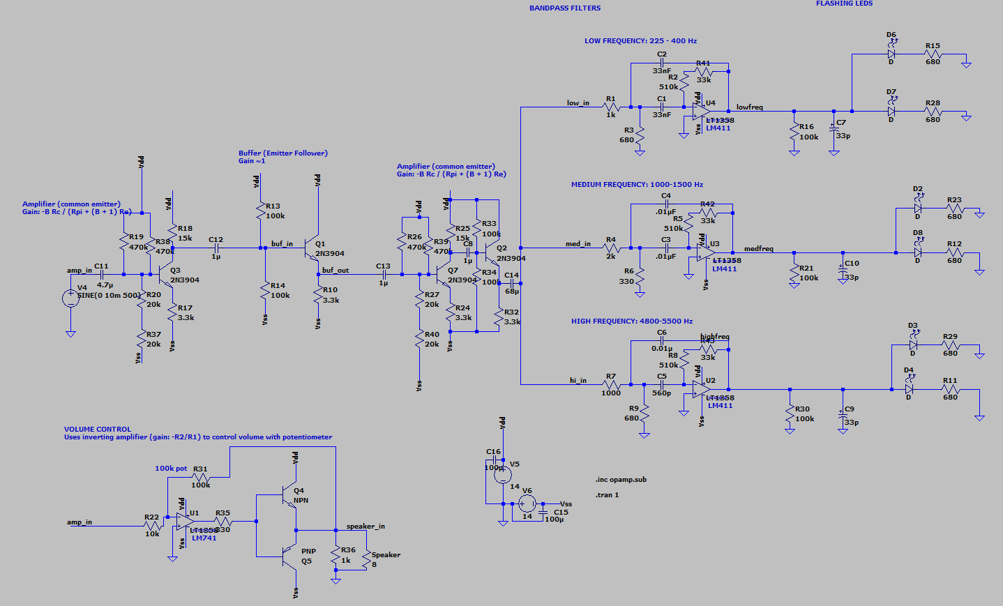
Full S^5 Schematic
Audio signals generally have very small amplitudes, and amplifying the signals ensures they can be adequately picked up by later stages of the design. One amplifier alone was not found to be sufficient, so a second amplifier stage was added. To prevent loading effects, a buffer in an emitter follower configuration was used in between stages. An operational amplifier could produce a better amplifier (more linear, and with higher gain) - but we didn’t have enough of that component. Darlington transistors could replace one of the transistors, for even higher gain, and to simplify construction. But this configuration is good enough.
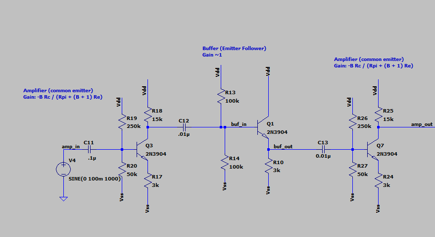
Transistor Amplifier Stage
We used a common emitter with degeneration topology for its high gain and favorable output impedance. A DC blocking capacitor was connected to the signal to prevent loading, and two biasing resistors were employed to maintain a DC operating point of 5 volts at the base. A design using degeneration was chosen to improve the gain’s linearity across a wide range of audio frequencies. Although degeneration decreases the gain, it allows for better input impedance and linearity of gain, especially for higher frequencies. The 2N3904 transistor was selected for its availability and high amplification factor Beta. The gain of one common emitter amplifier with degeneration was calculated as follows:
$A_v=\frac{-\beta R_C}{r_\pi + R_E(\beta+1)}=5$
With both stages, the resulting gain is 25, allowing for considerable amplification. In between each amplifier and buffer stage, a blocking capacitor was added to the output to remove any DC bias. An additional buffer was added between the last amplifier stage and the filters to prevent any further loading effects.
The amplified signal then needed to be filtered into one of three bands: low, medium, and high frequency. Operational amplifiers were used to make active bandpass filters. Active filters tend to be more sensitive and have a tighter passband than passive filters, which was valuable since the frequency ranges were small. The topology we used controlled the bandpass tightly compared to simpler topologies. Along with gain calculations, we used a MATLAB program to select resistor and capacitor values.
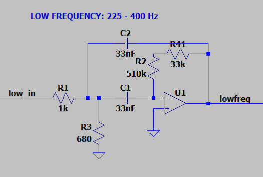
Implemented filter
The filtered signal is then sent to the LEDs for display. If the signal has passed through the low-frequency filter, it is sent to the red LED; for the medium-frequency, it is sent to the yellow LED; and the high frequencies are sent to the green LEDs.
Because an LED is a diode, it has a forward “on” voltage of approximately 0.6 volts. If a signal does not pass through the bandpass filter, its maximum voltage will surely be less than 0.6 volts - therefore, the LED is not active, and it will not be illuminated. Signals that do pass through the bandpass filter are large enough to activate the LED (amplitude larger than 1.2 V), and as such will be represented.
Passing the signal output directly to the LED is possible because the opamp has very low output impedance - an ideal opamp’s output impedance is zero. A series resistor is added to protect the LED from overcurrent. LEDs are not limited by frequencies in the audio range, meaning that it will be able to switch on and off with the input signal. This allows the lights to flash literally in tune with the music. However, given that the human eye can only process about 60 frames per second, the flashing will be so fast that the user will not notice, and simply see a constantly lit bulb.
I realize that driving an LED with an audio signal is bad practice - if I had more time I’d probably design a circuit that uses a transistor as a switch to turn on the LED, which would make the circuit more reliable since you could tune the threshold value depending on the transistor’s characteristics.
Volume control was also added to optimize the audio experience. An inverting amplifier was implemented using an operational amplifier with a potentiometer as the feedback resistor, Rf.
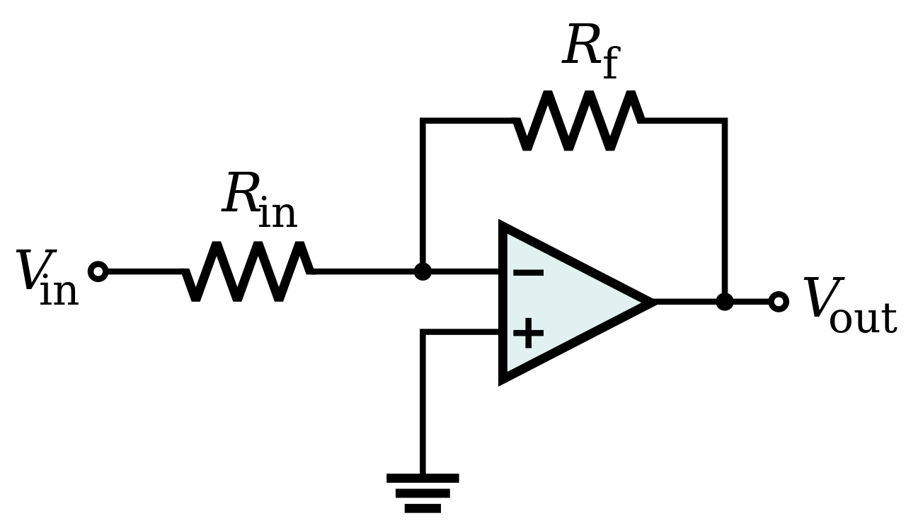
Inverting amplifier configuration using an operational amplifier
The gain equation for such an inverting amplifier is:
$A_v=-\frac{Rf}{Rin}$
Because the gain is negative and the input wave is a sine wave, the amplifier produces a 180 degree phase shift, which does not affect the final output. Utilizing the inverting amplifier, however, allows for varying Rf down to zero using a potentiometer, which means the system could be muted. A non-inverting amplifier, with gain always greater than one, would not have allowed for muting or lower volumes than the input. An active amplifier was selected for its high gain, linearity, and low output impedance. Only four LF411 operational amplifiers were available; with three being used for bandpass filters, this was the most important place to use the final opamp.
The LF411 operation amplifier was not able to produce enough current to drive the 8𝛺 speaker. A push/pull buffer was included in the output stage in order to drive the speaker. To avoid crossover distortion, the feedback in the inverting amplifier was connected to the output of the push/pull buffer rather than to the output of the operation amplifier.
Simulation
The amplifier is noninverting, because each common emitter stage is inverting. With a sine wave input of 100mV peak to peak, the output of the amplifier produces an amplitude of 3.2V peak to peak, or a gain of 32. This ensures small-voltage audio signals are amplified enough so they can be manipulated in the color amplifier later.
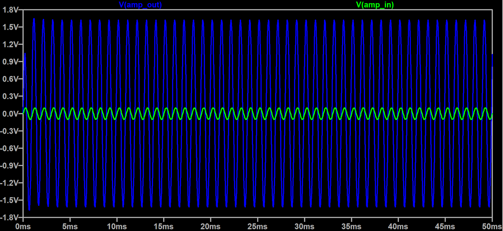
Amplifier input (green) and output (blue)
After each audio signal is amplified, it is passed to three bandpass filters that split the signal into three frequency bands: low, medium, and high. The gain of each bandpass filter was measured with LTSpice’s AC analysis tool.
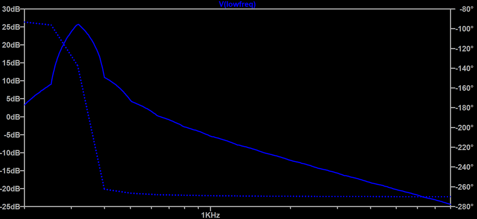 AC Analysis Results for Low-Frequency Bandpass Filter. Center frequency: 318 Hz. Most gain from 250 - 400 Hz.
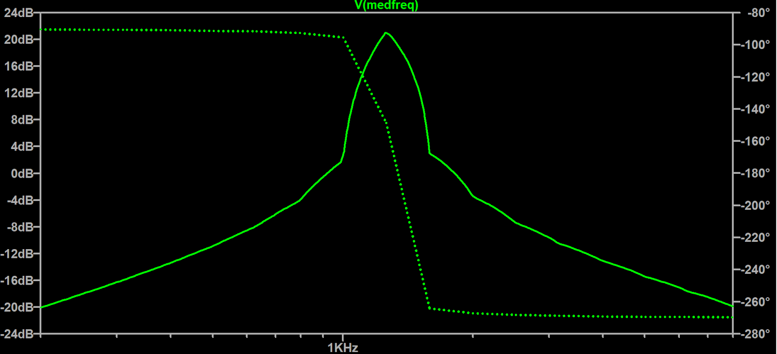 AC Analysis Results for Medium-Frequency Bandpass Filter.
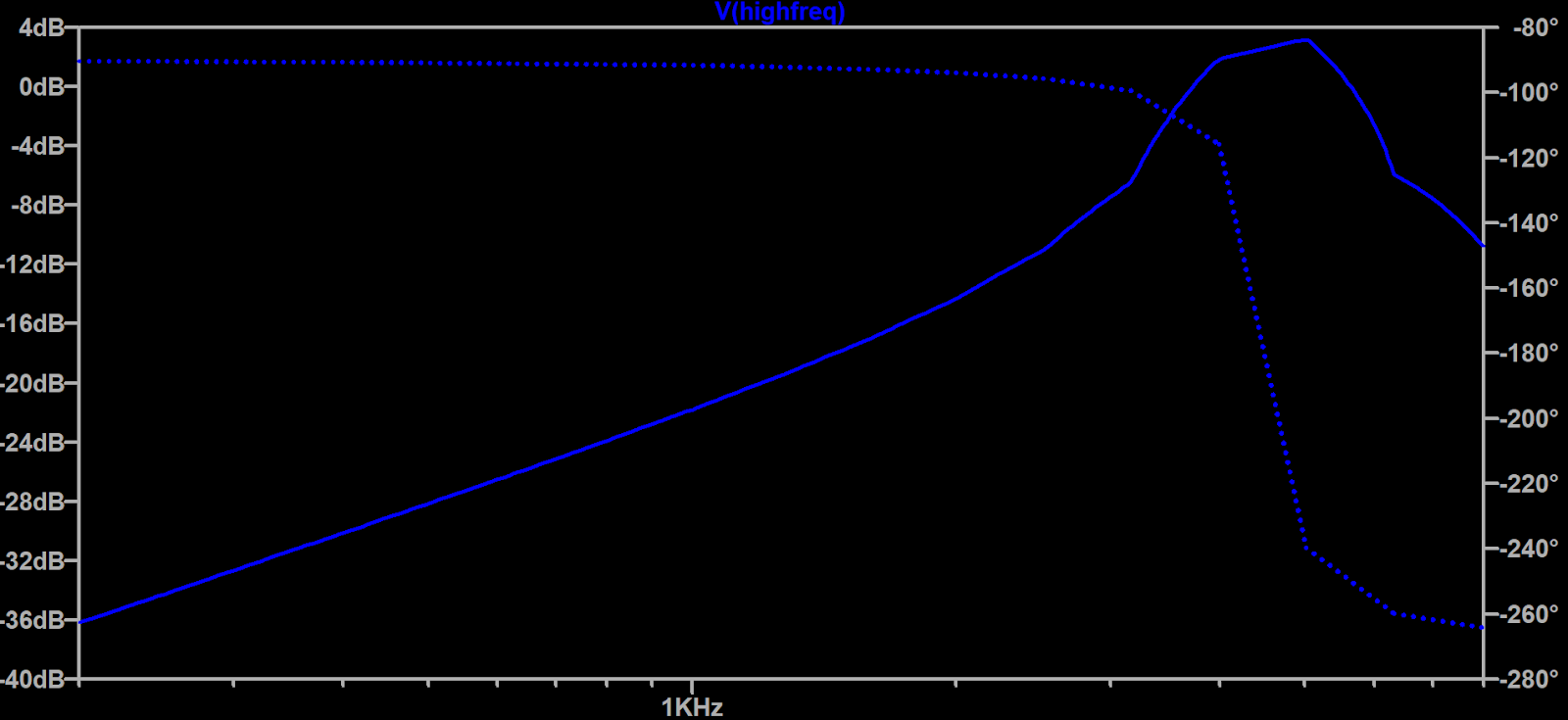 AC Analysis Results for High-Frequency Bandpass Filter. (The gain for the highest frequency filter isn’t nearly as much as the low and medium filters, which remains an issue.)
At first glance, there appears to be a beat frequency initially, which would severely impact circuit performance with varying amplitude.
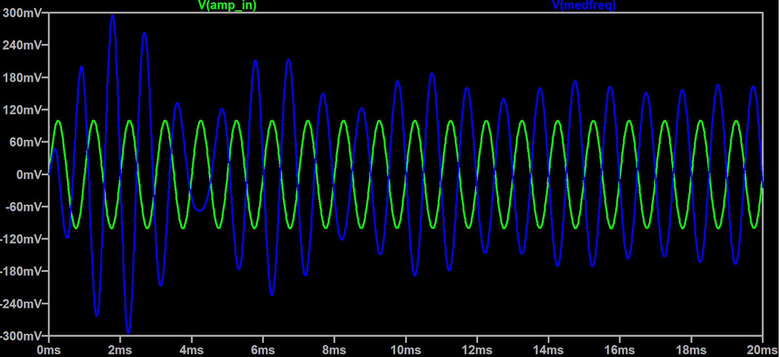 Apparent Beats Frequency at Bandpass Filter Output
We tested this by incrementing the frequency of the sine wave input as in the schematic below, which mimics a sequence of varying frequencies or notes in a piece of music.
It turns out that the transient only occurs on startup, for a very short and negligible amount of time, not when changing frequencies. As a result, the overall performance of the circuit will not be affected.
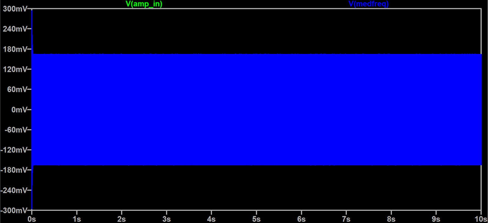 Result of Test with Sine Wave Input Sequence
Constructed Device
The device was constructed on a single breadboard
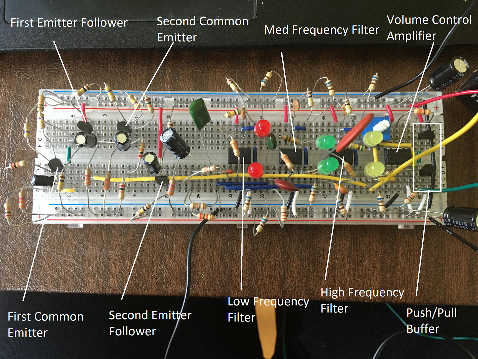 Active Components in the Built Circuit
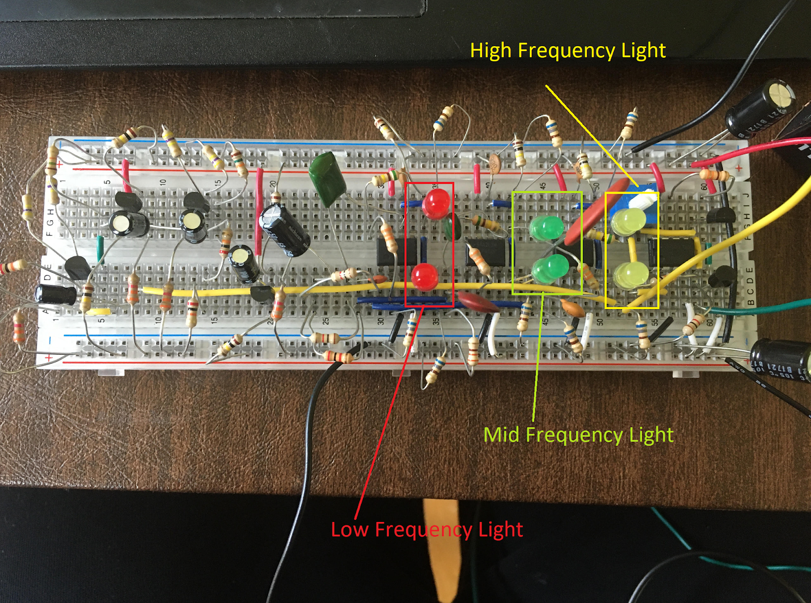 Light/Frequency band correspondence in the built circuit
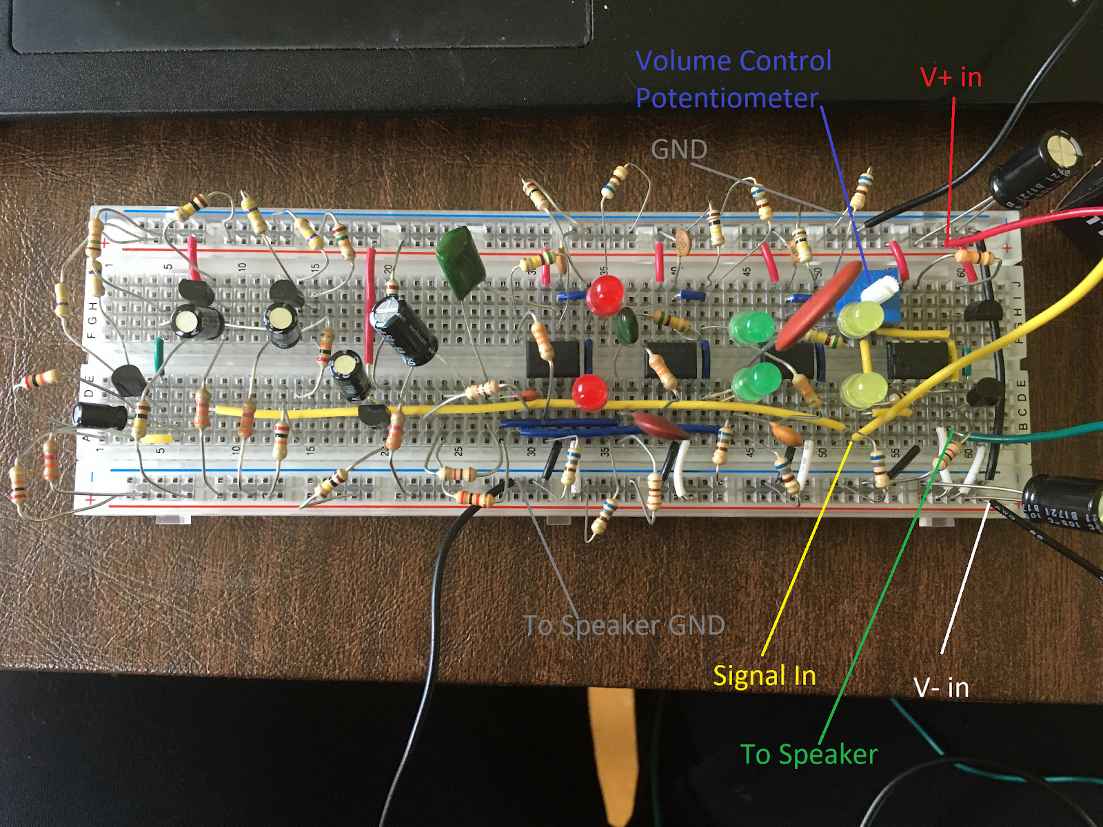 Circuit I/O
In order to get a sound signal from the laptop into the circuit, we modified an old headphone cable. The cable fit into the audio jack on the laptop, and the plan was to solder solid-core wires to the wires in the cable and connect the solid-core wires to the breadboard. This was complicated, since the wires were enamel coated and needed to be melted off using a soldering iron (don’t try this at home…).
Some discussion
Bandpass Filters
Designing accurate bandpass filters was a challenge. As previously discussed, the filter topology was chosen to achieve a tighter passband. The R1 and R2 input resistors were chosen such that R1 was slightly larger than R2, and the R3 resistor was chosen to be very large. The center frequency of such a filter can be calculated as:
$f_r=\frac{1}{2\pi\sqrt{R3(R1 // R2)C1C2}}$
And R1, R2, and R3 were chosen accordingly, and tweaked based on simulation.
Where possible, C1 and C2 were set to have the same value for simplicity, but this was only possible for low and medium frequencies. For the high frequency, using the calculated value would have resulted in a high-pass filter with a linear relationship between frequency and gain rather than a bandpass filter. As a result, the values for C1 and C2 were differentiated and selected using simulation - C1 was chosen to be 10nF, and C2 560pF.
Parts Selection
Parts availability was difficult. We did get a kit of components (since the class was virtual), but it only had about a quarter of the capacitors listed on the parts summary, which would have made our design impossible, even after making edits to reflect the parts that were actually in the kit. Fortunately, Nathaniel was able to pick up additional capacitors from his high school electronics teacher. Only four operational amplifiers were provided, and these were best used for the active bandpass filters and volume control. Although the kit’s parts summary listed four LM411s, there were only three LM411s and one LM741. The LM741, first designed and manufactured in 1968, has been deprecated, because modern operational amplifiers have better specifications. In order to prevent any discrepancies between filters, the LM411s were used for the bandpass filters, which is an application requiring more precision than volume control, for which the LM741 was used. If more operational amplifiers were available, the transistor amplifier could have been replaced, which would improve circuit performance because of the linearity and high gain of op-amp amplifiers.
Power Supply Integrity
Finally, during the construction process, it was found that the speaker played a sound with distortions, and it was unclear why the distortions were occurring. Adding a decoupling capacitor between ground and Vdd and ground and Vss resolved this issue, and the schematic was updated to reflect this change.
In Conclusion
This project was interesting because we were able to connect the EE concepts we learned in class with visualization of sound. We successfully implemented frequency-selective lights and volume control, despite limitations on parts (both intended, such as the limited number of operation amplifiers, and unintended, such as the missing capacitors), and successfully constructed an adapter to allow the color organ to play music from any device that includes a standard headphone jack.
What’s next? Now that we know that the circuit works, it could be cute to design and lay out some PCBs (and give them as gifts?). Building a circuit on a PCB is more stable than a breadboard, since it gets rid of a lot of the faulty connections and parasitic capacitance. The LEDs for each band could also be more tuned with regards to gain to equalize the amount of time each LED is lit- the low frequencies are very prevalent in music, but high frequencies, not so much.
A more sophisticated color organ could also achieve different light flashing effects, for example by implementing variations of volume or duration using pulse width modulation in conjunction with the Arduino software board or a 555 timer, allowing the lights to fade in and out at the beginning and ends of notes in an appealing manner.
Video
And since you’ve made it to the end, you’re probably wondering what it looks like! Videos here:
Comments